
新闻活动
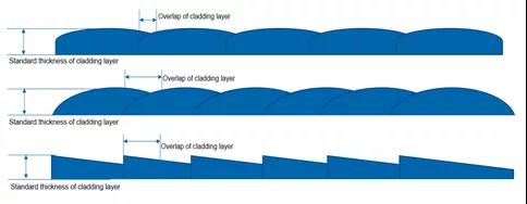 FIGURE 1. Laser beam uniformity affects lapping in the cladding process.
As reported here, a symmetrical structure was designed by bonding two submounts on the top and bottom of the heatsink to reduce the SMILE effect by balancing the packaging-induced stress. The 95% measured SMILE value in volume production was less than 2 µm. Low-SMILE vertical stacks made of 32 laser bars, each bonded on a microchannel cooler (MCC), were designed and characterized. A 2 × 20 mm2 rectangular beam of 6 kW continuous-wave (CW) output power with a beam uniformity of 90% was demonstrated.
This kind of rectangular high-power laser beam from low-SMILE laser bars is widely used in laser cladding applications. By adding cladding material (composite metal powder) on the surface of the metal substrate, laser cladding uses a high-energy-density and high-uniformity laser beam to melt cladding material together with the metal substrate surface to form a liquid metal molten pool, which is naturally cooled and solidified to form a metallurgically bonded material cladding layer on the substrate surface. This new material cladding layer can significantly improve the wear resistance, corrosion resistance, heat resistance, oxidation resistance, and electrical properties of the substrate material surface to achieve the purpose of surface modification or repair, meet the specific performance requirements of the material surface, and save materials cost.
Laser cladding process efficiency is greatly affected by the uniformity of the laser beam (including the SMILE of the laser source). Uniform laser beam energy distribution can lead to a good processing pool. Given a standard-thickness cladding layer, a high-uniformity laser beam can achieve smooth surface cladding through a lower amount of overlap. However, when using a laser beam with high SMILE, more overlaps are needed to make up for cladding layer thickness differences caused by nonuniform laser beam energy.
FIGURE 1. Laser beam uniformity affects lapping in the cladding process.
As reported here, a symmetrical structure was designed by bonding two submounts on the top and bottom of the heatsink to reduce the SMILE effect by balancing the packaging-induced stress. The 95% measured SMILE value in volume production was less than 2 µm. Low-SMILE vertical stacks made of 32 laser bars, each bonded on a microchannel cooler (MCC), were designed and characterized. A 2 × 20 mm2 rectangular beam of 6 kW continuous-wave (CW) output power with a beam uniformity of 90% was demonstrated.
This kind of rectangular high-power laser beam from low-SMILE laser bars is widely used in laser cladding applications. By adding cladding material (composite metal powder) on the surface of the metal substrate, laser cladding uses a high-energy-density and high-uniformity laser beam to melt cladding material together with the metal substrate surface to form a liquid metal molten pool, which is naturally cooled and solidified to form a metallurgically bonded material cladding layer on the substrate surface. This new material cladding layer can significantly improve the wear resistance, corrosion resistance, heat resistance, oxidation resistance, and electrical properties of the substrate material surface to achieve the purpose of surface modification or repair, meet the specific performance requirements of the material surface, and save materials cost.
Laser cladding process efficiency is greatly affected by the uniformity of the laser beam (including the SMILE of the laser source). Uniform laser beam energy distribution can lead to a good processing pool. Given a standard-thickness cladding layer, a high-uniformity laser beam can achieve smooth surface cladding through a lower amount of overlap. However, when using a laser beam with high SMILE, more overlaps are needed to make up for cladding layer thickness differences caused by nonuniform laser beam energy.
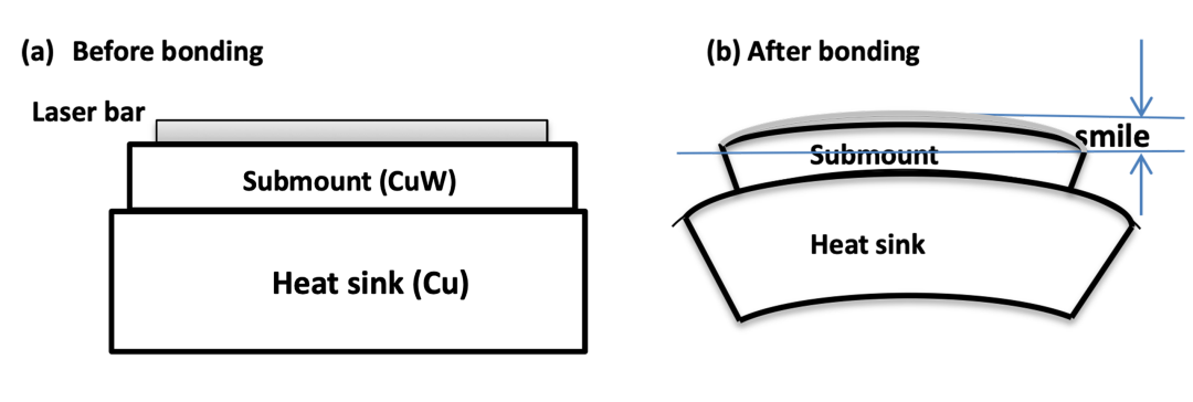 FIGURE 2. Schematic of a laser bar bonded on a CuW carrier sitting on an MCC heatsink with AuSn solders before bonding (a) and after bonding (b).
Compared to the HMCC, the SMILE value of a 1 cm bar is dramatically reduced by bonding another CuW submount below a HMCC to form a nearly symmetrical structure to balance the packaging-induced stress forced on the top and bottom of MCC, as shown in Figure 3 (called DMCC).3, 7 In this way, both the top and bottom sides of a MCC shrink at the same percentage during cooldown, keeping the packaging-induced stress forced on the top and bottom of a MCC in balance; this results in a smaller deformation of the MCC and minimizes the SMILE value of the 1 cm bar. Compared to the HMCC, the SMILE value of the DMCC is reduced from 10 to 15 μm to less than 2 μm. Figures 4 and 5 show the simulation results and the measured SMILE values of 1 cm bars based on HMCC and DMCC.
FIGURE 2. Schematic of a laser bar bonded on a CuW carrier sitting on an MCC heatsink with AuSn solders before bonding (a) and after bonding (b).
Compared to the HMCC, the SMILE value of a 1 cm bar is dramatically reduced by bonding another CuW submount below a HMCC to form a nearly symmetrical structure to balance the packaging-induced stress forced on the top and bottom of MCC, as shown in Figure 3 (called DMCC).3, 7 In this way, both the top and bottom sides of a MCC shrink at the same percentage during cooldown, keeping the packaging-induced stress forced on the top and bottom of a MCC in balance; this results in a smaller deformation of the MCC and minimizes the SMILE value of the 1 cm bar. Compared to the HMCC, the SMILE value of the DMCC is reduced from 10 to 15 μm to less than 2 μm. Figures 4 and 5 show the simulation results and the measured SMILE values of 1 cm bars based on HMCC and DMCC.
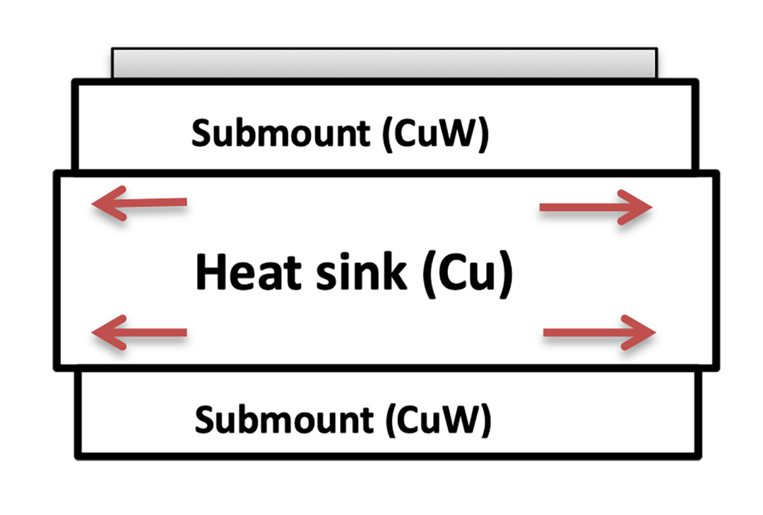 FIGURE 3. Schematic of DMCC in which two submounts are bonded on the top and bottom of a MCC with AuSn solders.
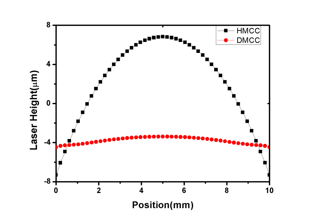 FIGURE 4. Simulated SMILE shape of a 1 cm laser bar bonded on HMCC and DMCC.7
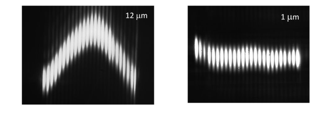 FIGURE 5. The measured SMILE shape and value of a 1 cm laser bar, each bonded on HMCC (12 μm) and DMCC (1 μm).6, 7
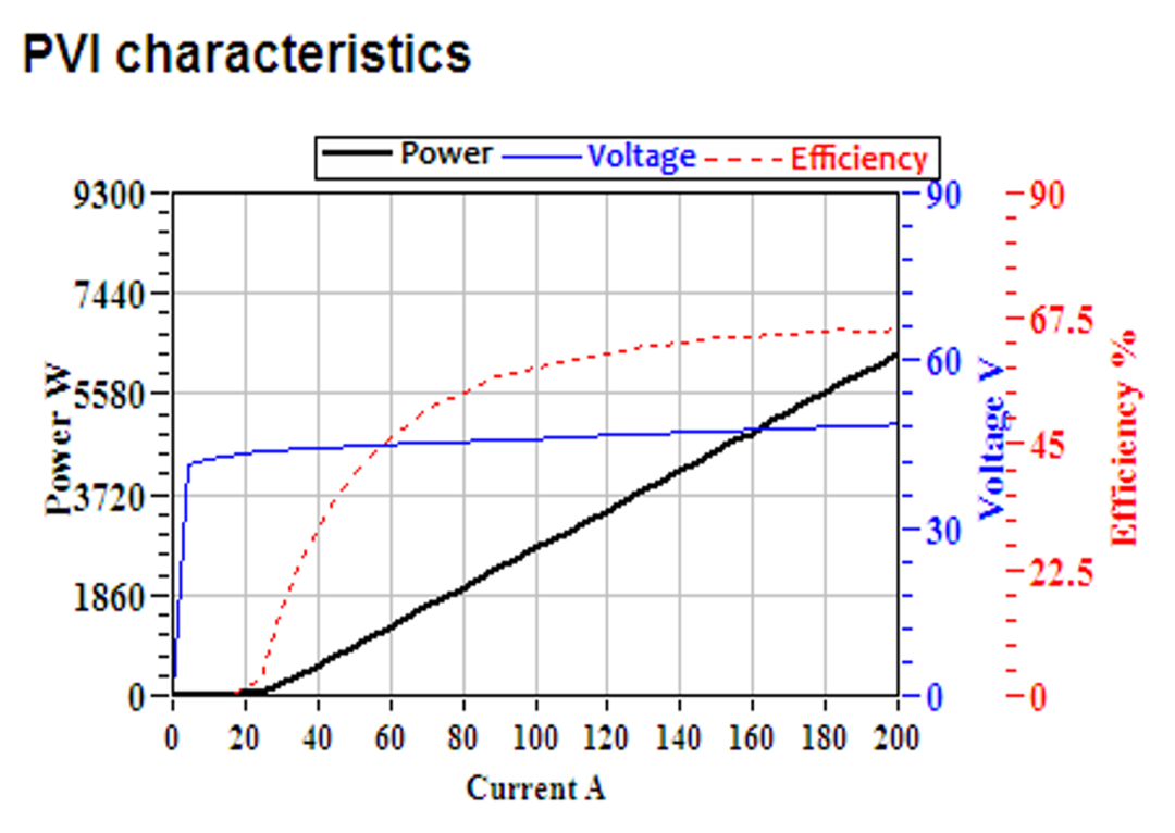 FIGURE 6. Light-current-voltage (LIV) testing results for a 32-bar vertical stack based on DMCCs.
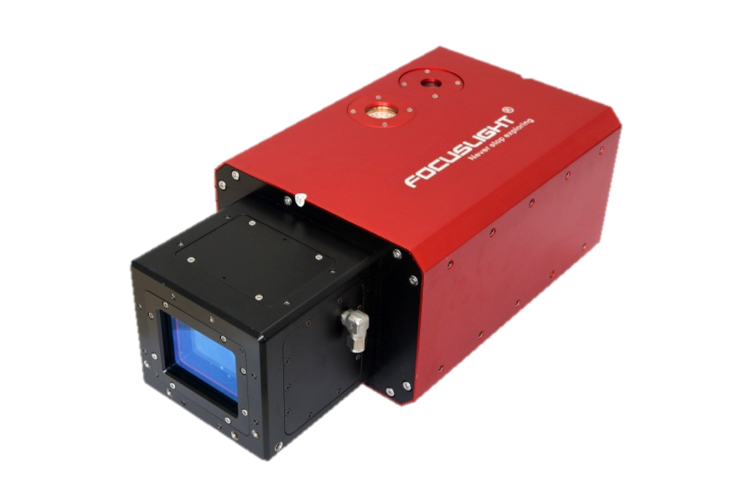 FIGURE 7. A rectangular-beam system.
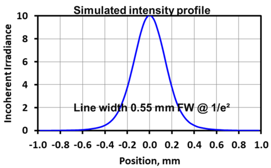
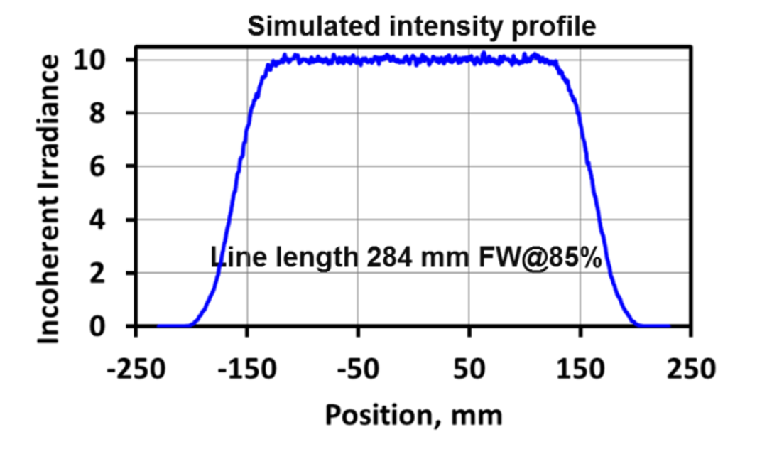 FIGURE 8. Simulated intensity profile of a 32-bar vertical stack in the fast axis (a) and the slow axis (b).
Using a low-SMILE DMCC packaging structure, the beam profile of a rectangular spot laser can be greatly improved, including the uniformity of beam length, the shape of the beam, and so on. Figure 9 shows laser beam images of industrial stacked arrays produced by high-SMILE DMCCs (average SMILE values from 2.8 to 3 μm) and low-SMILE DMCCs (average SMILE value from 0.7 to 1 μm). It can be clearly seen that after the fast-axis collimation of the high-SMILE DMCC vertical stack, laser beams from adjacent bars at the 30 cm distance will not be parallel or even be crossed (see Fig. 9a). However, when a low-SMILE DMCC vertical stack is used, the laser beams of the adjacent bars show good parallelism at the 30 cm distance after fast-axis collimation (see Fig. 9b).
FIGURE 8. Simulated intensity profile of a 32-bar vertical stack in the fast axis (a) and the slow axis (b).
Using a low-SMILE DMCC packaging structure, the beam profile of a rectangular spot laser can be greatly improved, including the uniformity of beam length, the shape of the beam, and so on. Figure 9 shows laser beam images of industrial stacked arrays produced by high-SMILE DMCCs (average SMILE values from 2.8 to 3 μm) and low-SMILE DMCCs (average SMILE value from 0.7 to 1 μm). It can be clearly seen that after the fast-axis collimation of the high-SMILE DMCC vertical stack, laser beams from adjacent bars at the 30 cm distance will not be parallel or even be crossed (see Fig. 9a). However, when a low-SMILE DMCC vertical stack is used, the laser beams of the adjacent bars show good parallelism at the 30 cm distance after fast-axis collimation (see Fig. 9b).
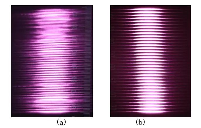 FIGURE 9. Laser images at 30 cm from high-SMILE DMCC vertical stack (a) and low-SMILE DMCC vertical stack (b) collimated by FAC lenses.
Using these two different laser stacks and passing through the same optical system to form a 2 × 20 mm2 laser beam, we can also clearly see the influence of SMILE on the laser beam, as shown in Figures 10a and 10b, respectively. These indicate the laser beam state when the industrial stacked array produced by high-SMILE DMCCs or low-SMILE DMCCs reaches a 2 × 20 mm2 laser beam through the optical system. The uniformity of the laser beam in the length direction of high-SMILE DMCCs is only 83.7%, while that of low-SMILE DMCCs is 93.5%. Since no slow-axis homogenizer is used, the uniformity could also be influenced by the intensity nonuniformity of emitters with a bar and the current dependent near field of each emitter. The high-SMILE DMCC products have a negative impact on the final beam uniformity and energy distribution, and may affect the laser application process.
FIGURE 9. Laser images at 30 cm from high-SMILE DMCC vertical stack (a) and low-SMILE DMCC vertical stack (b) collimated by FAC lenses.
Using these two different laser stacks and passing through the same optical system to form a 2 × 20 mm2 laser beam, we can also clearly see the influence of SMILE on the laser beam, as shown in Figures 10a and 10b, respectively. These indicate the laser beam state when the industrial stacked array produced by high-SMILE DMCCs or low-SMILE DMCCs reaches a 2 × 20 mm2 laser beam through the optical system. The uniformity of the laser beam in the length direction of high-SMILE DMCCs is only 83.7%, while that of low-SMILE DMCCs is 93.5%. Since no slow-axis homogenizer is used, the uniformity could also be influenced by the intensity nonuniformity of emitters with a bar and the current dependent near field of each emitter. The high-SMILE DMCC products have a negative impact on the final beam uniformity and energy distribution, and may affect the laser application process.
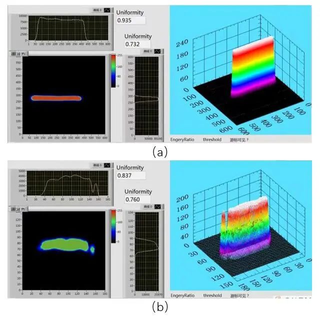 FIGURE 10. Final output laser beam produced by a high-SMILE DMCC vertical stack (a) and a low-SMILE DMCC vertical stack (b).


始终处于活动状态


 返回
返回