本文原发表于《Laser Focus World》英文版2021年1月刊。
摘要:
半导体激光器因其高功率和高可靠性的特点,已被广泛应用于表面处理工艺。长期以来,人们一直认为高功率半导体激光器由于近场非线性效应(SMILE)造成光束质量较差,不适合用于激光熔覆。降低SMILE效应的两种传统方法是:1. 用铟界面材料封装半导体激光器,以减少热诱导应力,从而降低SMILE;2. 对于每一个巴条,使用两个独立的FAC透镜来做准直,也可以降低SMILE。这两种方法都有各自的局限性:铟封装半导体激光器由于铟材料的热疲劳、热迁移和电子迁移的缘故,可靠性相对较低;而用两个FAC透镜进行准直,对于某些应用来说,光学设计过于复杂。
通过DMCC的特殊封装结构设计,炬光科技实现了1 µm的低SMILE值,81%的良品率和CW 200W/bar的可靠输出功率,并分别形成了线光斑产品(6KW Activation Line)和矩形光斑产品(6KW DLight)。前者可以形成在285mm x 0.55mm的线型光斑,均匀度为86%。后者可形成14mm x 2mm的矩形光斑,均匀度超过80%。
High-power, low-SMILE vertical stack diode laser bars
enable better laser cladding
A low near-field nonlinearity (low-SMILE), 32-bar diode stack produces a 6 kW uniform flat-top beam for cladding applications.
WEIYI GU and LEI CAI
FOCUSLIGHT TECHNOLOGIES INC.
High-power diode lasers play a major role in materials processing. Compared to conventional carbon dioxide (CO2) lasers, high-power direct-diode laser sources have great advantages, such as high efficiency, low cost, wavelength versatility, and high reliability. High-power diode lasers, with a 9xx nm wavelength much shorter than that of CO2 lasers, increases the absorption of the metal surface and improves the melting efficiency.1 However, the large SMILE effect, of which the emitters are vertically displaced in a laser diode bar, causes poor output beam quality.2 Laser diode array bowing in the fast axis increases the geometrical line width of the output line when creating a line by collimating and focusing an emitting light from a laser array in the fast axis.3 The poor output beam quality of direct diode lasers is a large obstacle in industrial applications (see Fig. 1).4, 5
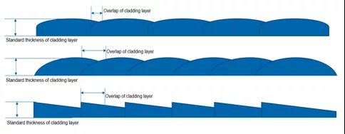
FIGURE 1. Laser beam uniformity affects lapping in the cladding process.
As reported here, a symmetrical structure was designed by bonding two submounts on the top and bottom of the heatsink to reduce the SMILE effect by balancing the packaging-induced stress. The 95% measured SMILE value in volume production was less than 2 µm. Low-SMILE vertical stacks made of 32 laser bars, each bonded on a microchannel cooler (MCC), were designed and characterized. A 2 × 20 mm2 rectangular beam of 6 kW continuous-wave (CW) output power with a beam uniformity of 90% was demonstrated.
This kind of rectangular high-power laser beam from low-SMILE laser bars is widely used in laser cladding applications. By adding cladding material (composite metal powder) on the surface of the metal substrate, laser cladding uses a high-energy-density and high-uniformity laser beam to melt cladding material together with the metal substrate surface to form a liquid metal molten pool, which is naturally cooled and solidified to form a metallurgically bonded material cladding layer on the substrate surface. This new material cladding layer can significantly improve the wear resistance, corrosion resistance, heat resistance, oxidation resistance, and electrical properties of the substrate material surface to achieve the purpose of surface modification or repair, meet the specific performance requirements of the material surface, and save materials cost.
Laser cladding process efficiency is greatly affected by the uniformity of the laser beam (including the SMILE of the laser source). Uniform laser beam energy distribution can lead to a good processing pool. Given a standard-thickness cladding layer, a high-uniformity laser beam can achieve smooth surface cladding through a lower amount of overlap. However, when using a laser beam with high SMILE, more overlaps are needed to make up for cladding layer thickness differences caused by nonuniform laser beam energy.
Low-SMILE laser bar based on DMCC
The traditional laser device based on a MCC is built with a laser bar bonded on a submount, such as copper/tungsten (CuW), and then on a MCC with a hard solder like gold/tin (AuSn), as shown in Figure 2a (called HMCC). Due to the coefficient of thermal expansion (CTE) mismatch between the laser bar (typical GaAs with 6.5 ppm/K) and MCC (typical copper with 16.5 ppm/K), a CuW submount with a CTE closely matched to that of a laser bar is used to minimize the packaging-induced stress on the laser bar after bonding.6 During cooldown from 287°C (AuSn melting temperature) to 25°C (room temperature), copper shrinks more than CuW because the CTE of copper is larger than that of CuW, resulting in a bowed laser bar/CuW/MCC for an asymmetrical structure (see Fig. 2b). Normally, the SMILE value of HMCC is almost 10–15 μm; the simulation results using finite element analysis and the experimental results will be shown later.
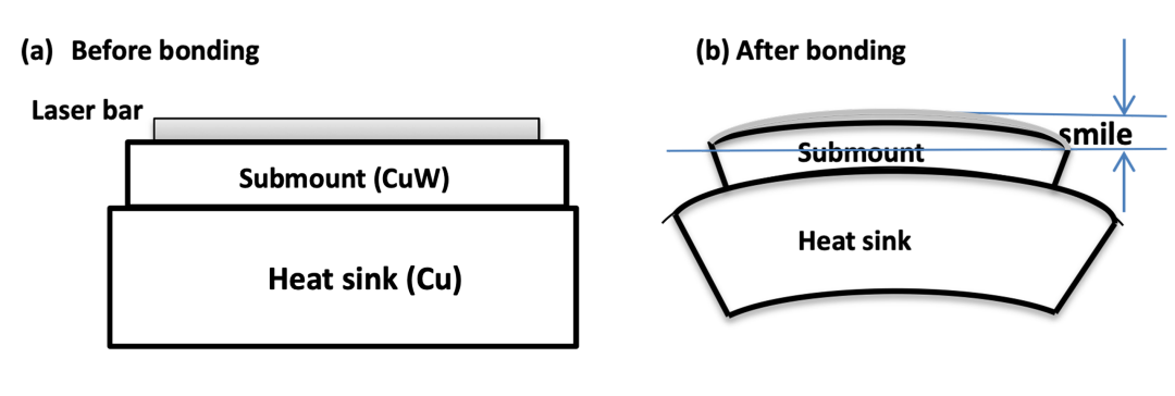
FIGURE 2. Schematic of a laser bar bonded on a CuW carrier sitting on an MCC heatsink with AuSn solders before bonding (a) and after bonding (b).
Compared to the HMCC, the SMILE value of a 1 cm bar is dramatically reduced by bonding another CuW submount below a HMCC to form a nearly symmetrical structure to balance the packaging-induced stress forced on the top and bottom of MCC, as shown in Figure 3 (called DMCC).3, 7 In this way, both the top and bottom sides of a MCC shrink at the same percentage during cooldown, keeping the packaging-induced stress forced on the top and bottom of a MCC in balance; this results in a smaller deformation of the MCC and minimizes the SMILE value of the 1 cm bar. Compared to the HMCC, the SMILE value of the DMCC is reduced from 10 to 15 μm to less than 2 μm. Figures 4 and 5 show the simulation results and the measured SMILE values of 1 cm bars based on HMCC and DMCC.
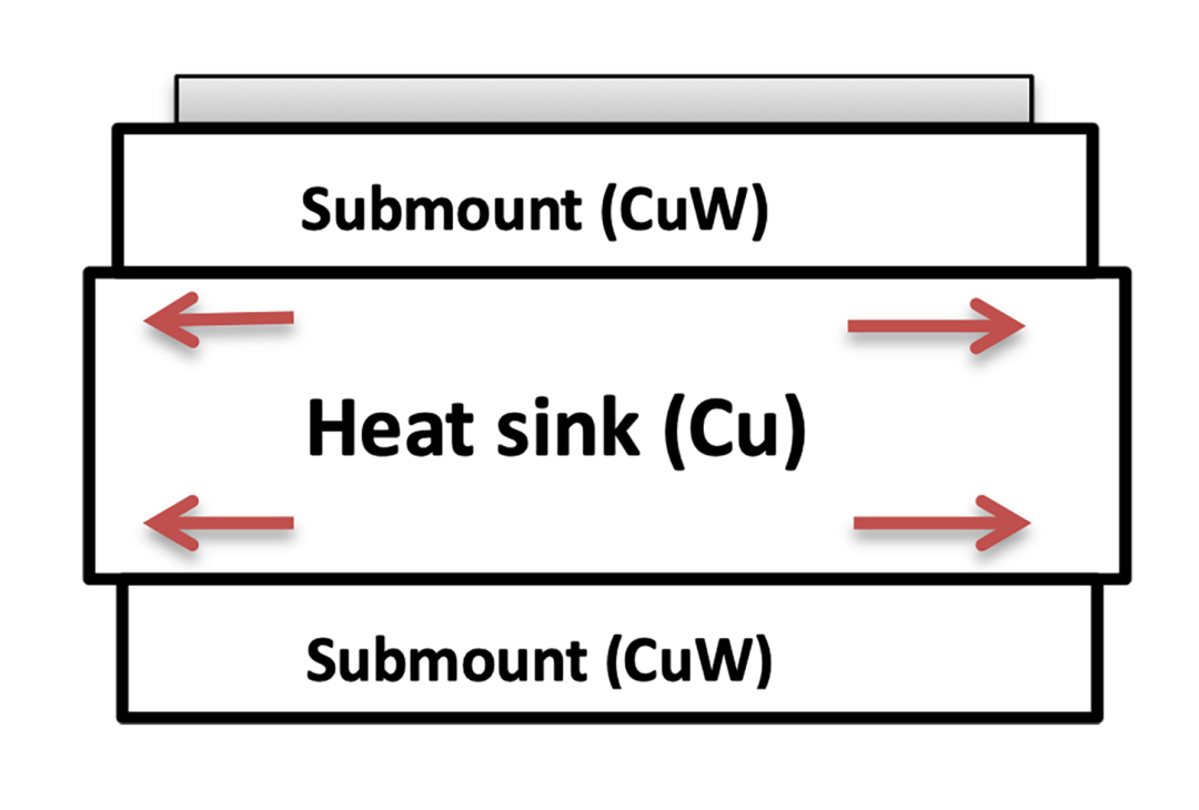
FIGURE 3. Schematic of DMCC in which two submounts are bonded on the top and bottom of a MCC with AuSn solders.
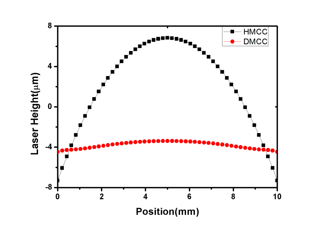
FIGURE 4. Simulated SMILE shape of a 1 cm laser bar bonded on HMCC and DMCC.7
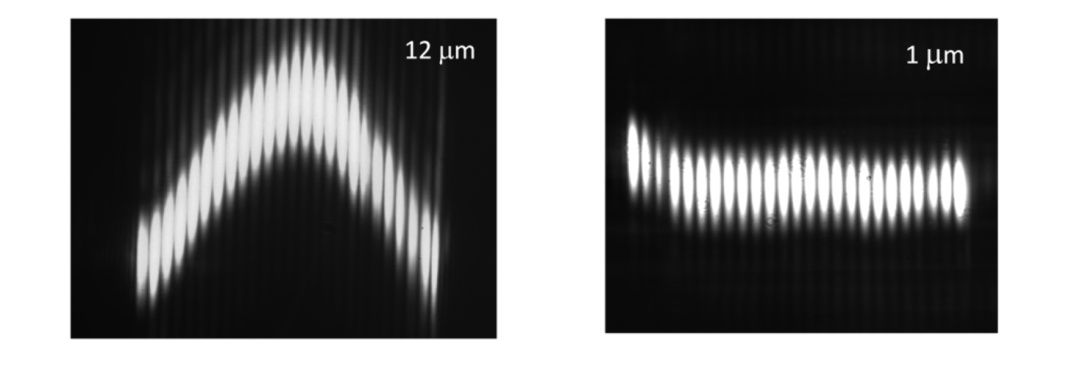
FIGURE 5. The measured SMILE shape and value of a 1 cm laser bar, each bonded on HMCC (12 μm) and DMCC (1 μm).6, 7
Vertical Stack with 32-bar DMCCs
To get a higher power, a vertical stack of 32 DMCCs was used to get the 6 kW output power at 200 A injection current. Test results for the 32-bar vertical stack are shown in Figure 6. A 2 × 20 mm2 rectangular beam was built with a 32-bar vertical stack (SMILE <2 μm) to produce 6 kW CW mode output power with a beam uniformity of more than 90% (see Fig. 7). The simulated intensity profile of the 32-bar vertical stack in the fast and slow axes are shown in Figures 8a and 8b, respectively. A 2 × 20 mm2 rectangular spot has many functions in materials processing, such as high-throughput scanning along the fast axis, due to the long edge of the spot. A flat-top spot guarantees the uniformity of the treated surface and is also perfect for obtaining a smooth brazing seam because the spot is narrow along the fast-axis direction.
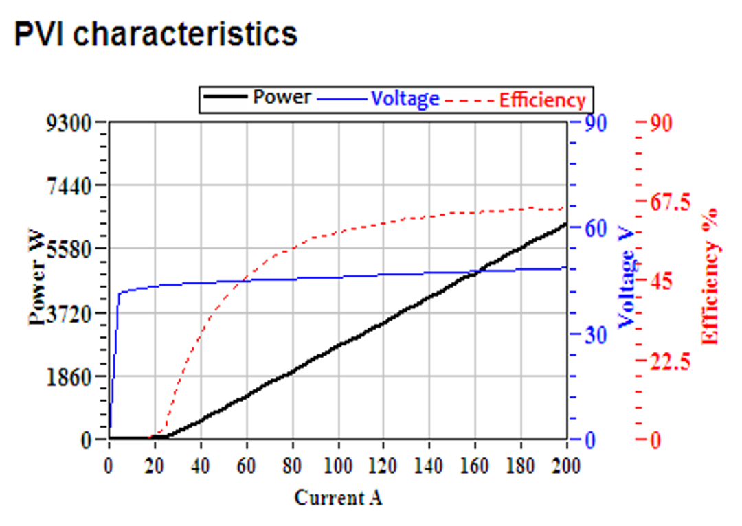
FIGURE 6. Light-current-voltage (LIV) testing results for a 32-bar vertical stack based on DMCCs.
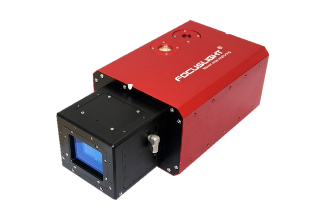
FIGURE 7. A rectangular-beam system.
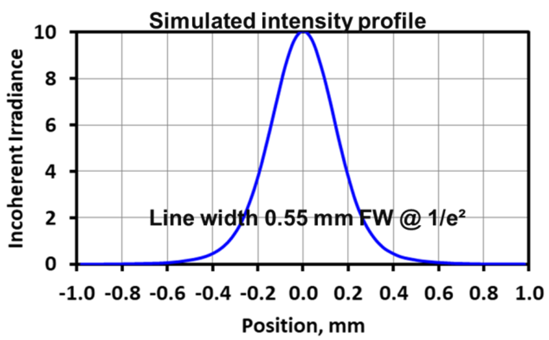
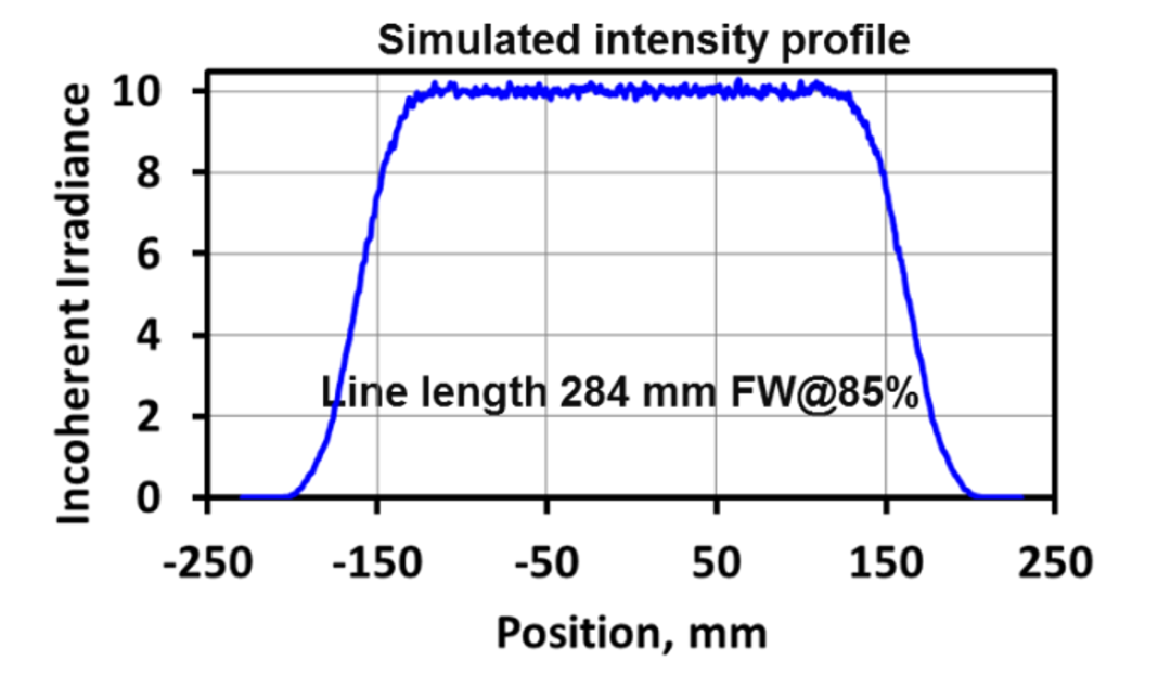
FIGURE 8. Simulated intensity profile of a 32-bar vertical stack in the fast axis (a) and the slow axis (b).
Using a low-SMILE DMCC packaging structure, the beam profile of a rectangular spot laser can be greatly improved, including the uniformity of beam length, the shape of the beam, and so on. Figure 9 shows laser beam images of industrial stacked arrays produced by high-SMILE DMCCs (average SMILE values from 2.8 to 3 μm) and low-SMILE DMCCs (average SMILE value from 0.7 to 1 μm). It can be clearly seen that after the fast-axis collimation of the high-SMILE DMCC vertical stack, laser beams from adjacent bars at the 30 cm distance will not be parallel or even be crossed (see Fig. 9a). However, when a low-SMILE DMCC vertical stack is used, the laser beams of the adjacent bars show good parallelism at the 30 cm distance after fast-axis collimation (see Fig. 9b).
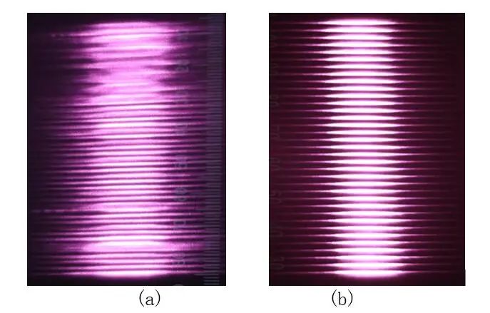
FIGURE 9. Laser images at 30 cm from high-SMILE DMCC vertical stack (a) and low-SMILE DMCC vertical stack (b) collimated by FAC lenses.
Using these two different laser stacks and passing through the same optical system to form a 2 × 20 mm2 laser beam, we can also clearly see the influence of SMILE on the laser beam, as shown in Figures 10a and 10b, respectively. These indicate the laser beam state when the industrial stacked array produced by high-SMILE DMCCs or low-SMILE DMCCs reaches a 2 × 20 mm2 laser beam through the optical system. The uniformity of the laser beam in the length direction of high-SMILE DMCCs is only 83.7%, while that of low-SMILE DMCCs is 93.5%. Since no slow-axis homogenizer is used, the uniformity could also be influenced by the intensity nonuniformity of emitters with a bar and the current dependent near field of each emitter. The high-SMILE DMCC products have a negative impact on the final beam uniformity and energy distribution, and may affect the laser application process.
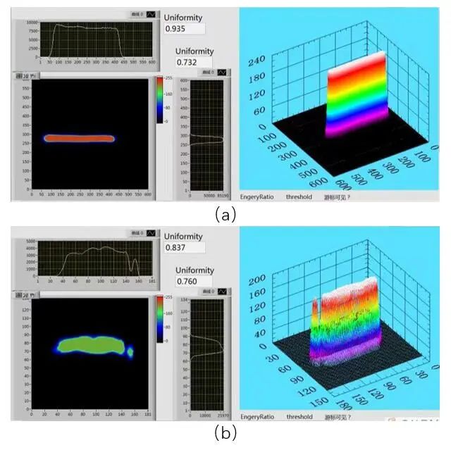
FIGURE 10. Final output laser beam produced by a high-SMILE DMCC vertical stack (a) and a low-SMILE DMCC vertical stack (b).
REFERENCES
1. H. Zhu et al., Opt. Laser Technol., 76, 101–105 (2016).
2. H. Zhang et al., Appl. Opt., 57, 28, 8407–8411 (2018).
3. C. Zah et al., Proc. HPD 2017, 9–10 (2017); doi:10.1109/hpd.2017.8261079.
4. L. Li, Opt. Lasers Eng., 34, 4–6, 231–253 (2000).
5. G. C. Rodrigues et al., Opt. Lasers Eng., 61, 31–38 (2014).
6. J. L. Hostetler et al., Proc. SPIE, 6456, 645602 (Feb. 2007).
7. H. Zhang et al., Opt. Eng., 57, 3, 036115 (2018).
Meet the authors
Weiyi Gu is Senior Manager of Laser Systems and Lei Cai is Senior Optical Design Engineer, both at Focuslight Technologies, Xi’an, China; e-mail: guwy@focuslight.com; www.focuslight.com.
About Focuslight:
Founded in 2007, Focuslight is a fast growing high-tech company committed to research, development and manufacturing of high power diode lasers. Headquartered in Xi’an, Shaanxi, China, Focuslight provides its products to a variety of different customers like OEMs, ODMs and system integrators in markets worldwide. With its extensive engineering capabilities from thermal, optical and mechanical design to die bonding, FAC assembling and fiber coupling to system integration, Focuslight is dedicated to providing customers with well-matched all-round solutions according to their actual needs. For more information, please visit www.focuslight.com.


 返回
返回